By Nathaniel Schwed, Senior Process Engineer
Learning Objectives
- Learn about Autodesk AutoCAD Plant 3D, which can help design engineers create a piping and instrumentation diagram (P&ID).
- Understand that by using a P&ID, the engineering drawings can be streamlined.
P&ID insights
- The most exciting development of AutoCAD Plant3D is the addition of “assemblies,” a method to preserve block configurations, sequential tags, and properties when copying between drawings and projects.
- Using these assemblies will revolutionize the drafting, review, and data verification processes of piping and instrumentation diagram (P&ID) development.
Autodesk AutoCAD Plant 3D has seen many advancements over the past decade, especially in the ability to copy components and duplicate drawings. The most exciting is the development of “assemblies,” a method to preserve block configurations, sequential tags, and properties when copying between engineering drawings and projects.
The use of these assemblies will revolutionize the drafting, review, and data verification processes of piping and instrumentation diagram (P&ID) development while achieving the horizontal data integration goals of Industry 4.0/Pharma 4.0.
In 2014, the act of copy-clipping and pasting in a different drawing was enough to disrupt the program’s ability to preserve unique tags. When an object was copied within a drawing, it would cause the newly created object’s tag to be suffixed with a question mark, prompting the user to provide a new tag.
However, this visual cue was not always provided when copying between drawings, and too often, duplicate tags were not identified or updated. To mitigate these errors and reduce database audits, users were encouraged to hold off tagging components until all copies of the untagged blocks were placed.
It is common to prefix tag numbers with an area designation, be it system, drawing number, or area number. When set up to automatically acquire that area designation to populate the tag itself, tags remained unique when copied between drawings as long as each drawing had a unique area designation property.
Upon insertion, they were immediately tagged with the new area number while retaining the existing sequential number. Tanks or other P&ID objects could be replicated onto separate drawings with a simple copy-clip-and-paste action. Blank drawings were created with the project’s template file, updated with the area designation in the drawing properties, and then populated by pasting the copied contents of the entire source drawing. The result was a drawing identical in appearance with sequential and loop numbers preserved, but all of the tags were unique due to acquiring a new area designation.
How to simplify P&ID solutions
Two main advances worked in parallel to support a more robust solution to copying drawing elements. First, as specialized projects were developed for different clients, client-specific “template” projects were set up with the same database structure for a given client. Plant 3D objects could be copied between projects as long as the destination project had the class definitions that matched the source project.
Second, there was a transition from SQL server-based projects to BIM360 cloud-based projects. This improved the ability to take the entire drawing file from one project and use the “copy drawing to project” function to import it into a new project as long as both projects came from the same template. While this did not automatically update the externally referenced title block, it functioned similarly to the ability of “copy drawing to project” to undo the removal of a drawing from the project to the recycle bin.
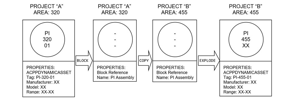
The preservation of data despite the blocks’ and drawing’s removal from a project led to an important discovery. If a P&ID asset block with data is turned into a block through the BLOCK command, it is removed from the database and otherwise loses all its properties.
However, if the EXPLODE command is run on this block, it returns to the project and populates the database with all the values and properties it had before being turned into a block. This carries new potential, functionality, viability and reliability in the form of the future for Plant 3D: assemblies.
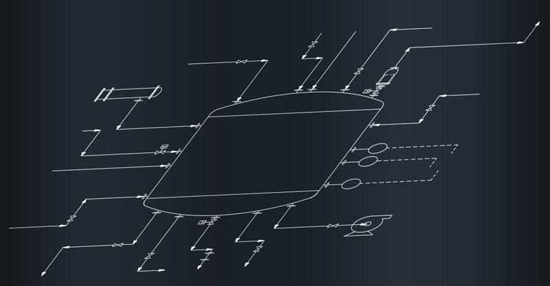
Assemblies are a collection of P&ID assets, including valves, lines, instrumentation and even equipment that have been turned into a block (see Figure 1). This block can be added to a user’s tool palette. This user can drop that block into another drawing, even a drawing in a different project for the same client. Because all projects for the same client use the same database structure, when the assembly block is exploded in its new drawing, all P&ID assets regain their tags and properties as if they were originally created in the new drawing.

A tool palette full of standard assemblies can also be shared with other users. While P&ID assets on a tool palette reference the project setup, regular blocks (including assemblies) must reference a source drawing. Therefore, all users need access to the source drawing to use the assembly.
However, there are cloud-based platforms (for example, UNIFI Labs) that can store AutoCAD blocks (including assemblies) and allow all users with access to the platform to use the block without having access to the original drawing in which the block was created.
For a long time, users have tried methods of turning a drawing into a generic template. Before the adoption of a smart P&ID program, these template drawings were commonplace, but in the years since, the struggle has been to create a template that is reliable and functional inside the Plant 3D environment. Assemblies are the solution. By the time a project goes to construction issue, datasheets for all assets should be available.
The properties of the P&ID components in the drawing can be updated from these datasheets with the manufacturer, the model number, process parameters and calibration data through either Plant 3D’s interface or Microsoft Excel. Once this drawing and all inserted data are approved, the drawing contents can be blocked as an assembly and added to a tool palette as an approved configuration. These assemblies can cover individual unit operations on a drawing like various filter carts or a preferred vendor’s water distribution skid, but they can also be used for an entire drawing, like standard instrumentation for an autoclave black box P&ID. The assemblies can then be used to create future drawings on the same project or a different project for the same client to lower design drawing effort.
Interconnecting the information
As more system or product manufacturers use Autodesk AutoCAD Plant 3D, users will be able to use the assemblies in drawings to populate the database with specification and calibration data, which in turn can be used to produce lists and datasheets. In addition, assemblies will reduce the time spent reviewing the drawings because CAD errors will be substantially reduced and the designs will have already been approved. All that remains will be to check the design for variations due to differing process conditions and load sizes.
The creation and maintenance of a database tied to a P&ID set is an important component of horizontal data integration. Assemblies for standard equipment ensure that the data is defined for all skid components from the moment the assemblies are added to a drawing. This enhances and preserves the existing capabilities of Plant 3D to create an interconnected database of assets like valves and instruments to be linked with and correspond to their pipelines and equipment. When an assembly is exploded, all assets regain horizontal data integration and acquire the tags and process information of the lines to which they are attached.

The use of templates does have its limits. Where assemblies excel at reproducing standard configurations, assemblies are not suited for systems with high variability in design. Complex systems, like fermentors and bioreactors, rarely have standard configurations as each unique process will have different requirements.
However, support and utilities systems will see the most success as assemblies are created for each major manufacturer. While Assemblies build an integrated model for the digital twin, Plant 3D does not allow for testing different inputs to predict and optimize outcomes or configurations. Assemblies will reduce the amount of time spent populating the database with individual instrument properties while establishing a strong starting point for the client to receive a living database of instrument and equipment data.
Read the article on the Consulting-Specifying Engineer website


