

As we discussed in our previous article, there are multiple variables that must be considered in the layout of a biopharmaceutical facility, and many of these variables are interdependent. The adoption of single-use systems (SUS) is allowing for a shift in the balance of those variables to enable smaller and more flexible facilities. This article will explore modern facility design options and configurations, and the realities of building a facility around the SUS process technology discussed last month.
Basic Principles Of SUS Facility Layout
Once we understand our basic constraints and have outlined our processes and risks completely, we can start positioning the equipment and the processes in the facility. Following are some basic layout techniques that will provide the adjacencies from the process core, or building blocks, of how a facility should look.
The actual process area should be limited to the space the operators need to interact with the equipment, and that should be kept to an absolute minimum. This classified Grade C space should house addition ports, connection points (including those for utilities), and sample ports only. This is the exposed “open” processing we discussed in our last article.
All large, fixed, stainless steel equipment needs to be in non-classified “gray” space. The gray space can include any fixed piping systems and manifolds. This is a key economic trade-off of space — unclassified grey space (@ $100-200/sq. ft.) versus Grade C space (@ $500-700/sq. ft.).
With SUS methods, the need for co-located wash rooms with floor drains and high moisture levels should be eliminated. Using process-integrated sterilizers is also unnecessary, since the process flow paths (vessels, tubing, and instruments) are the SUS. The only sterilizers that may be needed are the exit/decontamination sterilizers that will process biosafety level (BSL) 1-4 material or live cell culture prior to disposal.
Based upon the risk profile of the product, several process steps can be co-located in the same suite.
Generally, processes that use viral inoculation must separate a pre-viral (upstream) processing suite from the post-viral (downstream) processing suite as required. This separation is similar and required for all BSL levels. Processes at different BSL levels must be separated from one another (e.g., BSL-1 from BSL-2), even for the same product in a single-product facility.
SUS technology can eliminate the need for tanks for media and buffer prep, as well as the need for washing and cleaning of those vessels. The key is a controlled Grade C area to execute the dispensing and addition. Alternatively, one could buy premade media or buffer. Either way, the material needs to enter the processing area compliantly, not dragged in from a warehouse dispensary. Yet another alternative is to incorporate a flexible, portable “pop-up” plastic isolator (with negative HEPA pressure) to execute material dispensing (in a grey space) of media, buffer, or even a potent compound. This last option also reduces footprint, because it can allow a normal processing suite to function as a dispensary and eliminate another room/suite.
SUS technology precludes the need to move equipment around and replaces nearly all vessels under 1000 liters. Combined with the use of pre-sterilized hoses, ports, and aseptic connectors, SUS can also allow targeted rooms to become multiprocess, multifunctional, and multiproduct. This can further reduce the facility footprint, the number of rooms and airlocks, and internal traffic.
Layouts need to account for the support and orderly arrangement of single-use tubing sets and the skid and room ancillaries.
Implementing these considerations could result in having several parallel non-dedicated suites that can function as “flex-processing space.” These would be sized to accommodate the variety of processes, in order to maximize use and minimize idle time. These rooms must have the full complement of utilities for use and should include HEPA in/out (using bag-in/bag–out, or BIBO, filters) to allow them to accommodate wide product use.
In summary, we focus on the workflow of the operator, using SUS to consolidate the number steps, eliminate fixed vessels, use (cheaper) grey space for large or fixed tankage, incorporate flexible/disposable isolators, and keep media isolated/separated from the open processes. Now we have a concept to begin the layout.
Layout Rules And Options
In order to layout the facility, the EU and the FDA have provided enough guidance and recommendations to provide a starting framework.
The flow of people, equipment, raw material, products, and waste must always be in a unidirectional manner, which forces all personnel and components to enter clean, participate in the process, and exit. The facility layout should prevent travel against this direction, including movement between various suites. This is the first very clear safeguard against material/product cross-contamination between suites, as well as bioburden. If contamination arises, it will not be spread to other suites via personnel or other means — it will stay contained in that suite system. This concept necessitates that processing suites exist in parallel and that all aspects flow into the processing suite and out an exit path. The result is a process flow that prevents crossover and cross-contamination.
The entrance to any suite is always a clean corridor and increasing levels of EU–grade spaces, from CNC to D to C. Each change of grade contains an airlock to separate the grades (and suites) and provides a physical buffer so one grade minimizes the potential to contaminate the next.
The exits from all processing suites must provide a declining series of room/suite/airlock grades (C to D to CNC), with airlocks or air-sinks ultimately exiting into a “dirty corridor.”
Gowning is a clean activity and is always attached to the clean corridor, while degowning is a dirty activity and is attached to the dirty corridor. The gowning and degowning rooms must always be separate.
Because of the differing methods of decontamination/cleaning for people versus materials, people never share the airlock with a piece of equipment or material.
Any utility function, such as equipment preparation or storage, must be designated as a clean or dirty function and service the suites from one side, not both. As an example, if a skid is moved out of a suite for maintenance, it is a dirty function that enters a dirty corridor and travels into a service suite. The exit of that suite should be a cleaning/decontamination function that is accessible (after a series of airlocks) to the clean corridor, so the unit can be reused.
Ultimately, this concept forces a circular pattern of working from clean to dirty, dirty to retool/re-gowning, and a return to clean.
3 Basic Layout Models
Based on the constraints and regulatory rules discussed above, there are three basic layout models.
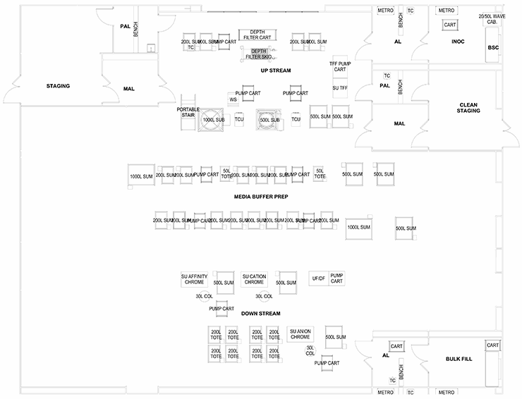
Train
A “train” of linear clusters of suites with a common corridor, each of which is geared for a specific process operation. This allows processing to start in the lead/upstream suite (e.g., bioreactor) and progress down the train (e.g., chromatography operations). When one product is in the downstream suite (e.g., chromatography), a new bioreactor can be running the upstream process of the product again in a campaign. This model is well-suited for several types of commercial applications, especially single-product non-potent compound.
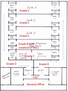
Stack
A “stack” of several larger, parallel multiple-purpose suites with a clean corridor on one side and a dirty corridor on the opposite side. This configuration isolates each suite via airlock systems, so one major process is performed at a time (e.g., all previral steps) and is contained. The product of that suite can be bagged or transferred for the post-viral process, to be performed in that suite (after decontamination) or another. This layout works best for commercial multi-product bio-production or for a contract manufacturer (CMO).
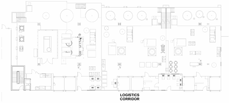
Ballroom
The last configuration involves a series of preparation suites leading to one large multipurpose “ballroom” that services several process and products. The ballroom will have several exit paths depending on the product bulk handling and packaging. This configuration is ideal for R&D and clinical production.
These configurations offer some generic layouts based on the regulations and constraints discussed above. The process engineer must work with a layout specialist or architect to decide which processes must be adjacent, separated, isolated, or combined. With the core defined, the balance of the facility can be detailed with support corridors, locker rooms, utility systems, and warehousing.
To read more go to http://www.bioprocessonline.com/doc/bioprocess-facility-design-layout-rules-and-configurations-0001
