

The Food and Drug Administration (FDA), led by Janet Woodcock, Director of the Center for Drug Evaluation and Research (CDER), is tirelessly and relentlessly promoting continuous manufacturing (CM) as the best opportunity to achieve its 21st Century Quality Vision of “…a maximally efficient, agile, flexible pharmaceutical manufacturing sector that reliably produces high-quality drugs without extensive regulatory oversight.”1
Research organizations formed from collaborations among leading universities, multi-national drug companies, and regulatory agencies have made great advancements in CM technology and have seen versions of their test bed models implemented in cGMP manufacturing environments.
The Center for Structured Organic Particulate Systems (C-SOPS), headquartered at Rutgers University, which now includes four major universities and over 40 industrial consortium member companies, was enlisted by Dr. Woodcock in May of 2015 to develop an “FDA Guidance in Continuous Manufacturing,” which will serve as a CM implementation guide for OSD manufacturers.
Less than one month ago, the FDA issued a draft guidance on emerging technologies, which included the formation of a group within CDER known as the Emerging Technology Team (ETT), intended to streamline submissions from pharmaceutical companies seeking approval of products manufactured using an emerging manufacturing technology, such as continuous processing.
The C-SOPS working group developing the FDA guidance is a collaboration of the world’s largest pharmaceutical companies. Major equipment manufacturers continue to develop CM processing equipment, open testing facilities, and contribute machinery and systems to C-SOPS for implementation in their research labs. Finally, as capital spending on CM technology continues to increase, engineering firms will play a critical role in ensuring that market adoption is not stalled because of poorly executed capital projects.
Engineering firms must have a comprehensive understanding of the differences between batch and continuous OSD operations, and take proper measures to ensure that their capabilities are aligned with the needs of the pharmaceutical industry in the ongoing emergence of CM. It is the responsibility of the engineering firm to modify the traditional OSD capital project design and execution strategy for CM.
Identification of business drivers is nearly always a responsible first step in planning a new facility or retrofitting an existing plant for a new manufacturing technology. In a CM initiative, drivers may include the accelerated development of a breakthrough therapy, the need to reduce cost of goods, or the introduction of more products at lower volumes aimed at gaining strategic access to emerging markets. In all cases, the definition of batch size is essential to the capacity analysis that must be developed at the onset of the program.
In traditional batch manufacturing, batch size would often correspond to major equipment volume or nominal capacity, for example, the 1,200-liter fluid bed processor or the 600-liter intermediate bulk container (IBC). In batch production, it is not uncommon for capacities to vary among unit operations, creating the need for work-in-process (WIP) inventory buffers between steps. The capacity analysis in batch operations is further complicated by a wide array of potential scheduling strategies, including varying degrees of campaigning. Batch production is time variant, and often relies on end point determination. Weigh/dispense, typically the first major operation in a batch facility, is driven by batch size, which the engineer uses to estimate staging requirements for major ingredients, as well as batch kits awaiting downstream processing.
The engineering team must approach a CM project from a different perspective. In CM, there are many acceptable approaches to batch definition, including run time, volume produced, or active pharmaceutical ingredient (API) lot. It may be acceptable to simply define batch size by throughput, and not commit to a specific quantity of product or duration of run time. The CM operation is characterized by throughput, typically in kg/ hr, which—in many ways—simplifies the capacity analysis. Unit operations are close-coupled and characterized by a common line rate of production. WIP inventory between connected unit operations is eliminated. Weigh/dispense is replaced by loss-in- weight feeders.
The need to analyze capacity and properly consider constraints will not be completely eliminated. A fundamental difference between batch and CM is understanding the time to reach steady-state, where operations are consistent “…over a period of time where all relevant process parameters and product qualities are not subject to variation outside of a defined range of values.”2 Similar to batch operations, equipment set-up and disassembly, as well as major and minor cleaning times, must be estimated in order to conduct meaningful capacity studies.
As the project moves into detailed design, the level of automation, the plant configuration, and the nature of design deliverables look very different in a CM project, versus traditional batch OSD.
The following paragraphs elaborate on how engineering firms may modify their detailed design approach for CM project execution, and why CM projects require more sophisticated design tools for proper execution.
AUTOMATION
The level of automation in batch OSD facilities varies greatly. Some clients use electronic batch record systems, which monitor critical parameters from each unit operation through a higher-level Distributed Control System (DCS). Based on the complexity of the batch record system, unit operations may require a permissive signal from the DCS to start operations. In this type of highly advanced system, each room would have a local operator station that would interface with the DCS. Also, all major equipment would have identified I/O interface with the DCS over a selected communication protocol, i.e. Fieldbus, ModBus, DH+. However, the equipment itself would still act as an island of automation. All set points and operational queues would be initiated from the local equipment control system.
Since a continuous manufacturing train needs to be properly tuned and the throughput of the close-coupled unit operations synchronized, the continuous equipment needs to not only be monitored, but controlled by the higher-level automation system. Each unit operation will still have an independent control system but set points and critical parameters will be input from the DCS and queues to delay, slow down, or pause will all be generated from the higher-level automation system.
In traditional batch operations, materials move between unit operations in IBCs. In a continuous operation, materials move via gravity or pneumatic transfer in a closed piping system between unit operations. In continuous operations, critical parameters (blend uniformity, moisture content, particle size) are measured and analyzed in real-time between unit operations to verify the system is operating within predefined control limits, i.e., the process is in specification. These measurements are collected utilizing process analytical technology (PAT) devices, which are installed in the transition piping between process equipment. The location of each PAT component is critical to ensure desired functionality, as well as accessibility for maintenance and calibration. Also, they require power and communication wiring back to the DCS, so determining wire-ways or conduit paths is an important coordination step in the design process.
EQUIPMENT MODELING
It is not uncommon for batch pharmaceutical facilities to compartmentalize or group unit operations into specific functional areas, i.e., granulation, blending, and compression. Furthermore, to facilitate training and scheduling and promote consistency, many organizations standardize unit operations, as well as the rooms that house them. For example, a standard compression module will always include the same make and model tablet press, deduster, and metal detector. Peripheral containers, scales, and furniture will be arranged in a standard configuration in the room. Personnel trained in compression operations will be familiar with all compression suites in the facility, and possibly the entire organization. The time required to add new modules is minimized, because standard designs and implementation documents already exist.
As these standard modules are configured in the facility the corresponding technical/mechanical spaces must be added adjacent to each process room. Technical areas support the auxiliary mechanical, electrical and plumbing (MEP) services, including vacuum pumps, air handling units (AHU’s), and dust collectors, as well as electrical and control panels associated with the process equipment.
The equipment arrangement in Figure 1 illustrates the use of standard processing rooms with adjacent technical areas in a traditional batch OSD facility.
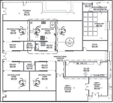
In CM, unit operations are close-coupled and reside in a common production room. Although this aspect of CM is favorable because it results in a significant reduction in CGMP space, it becomes difficult to arrange technical equipment in an ideal manner, with respect to desired adjacencies and proximities to associated process equipment. The technical area becomes a multi-operational space, similar to that of the production suite, and minimizing pipe and cable runs and ensuring proper accessibility and maintenance access to all equipment takes on a new form of challenge.
DESIGN TOOLS AND DELIVERABLES
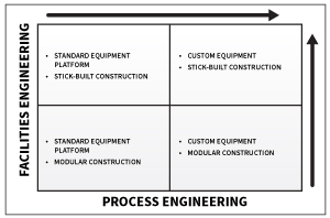
As illustrated by the preceding graph, the scale of engineering hours of labor and deliverables required to execute a capital OSD project varies depending on the level of equipment/ automation standardization and the degree to which modular facility construction is leveraged. If standard equipment/ automation is employed, such as the GEA ConsiGma continuous platform, then it makes sense to leverage vendor engineering, including Piping and Instrumentation Diagrams (P&IDs), as well as automation documentation—thereby minimizing the scope of process engineering services required from the engineering firm of record.
In contrast, if it is determined that some combination of vendor offerings provides a better-suited processing system for a particular product, then the engineering firm takes on a more significant process integration role, thereby increasing the scope of process engineering services required. These deliverables will most likely include detailed P&IDs, system architecture and connectivity diagrams, and detailed instrument, valve, and equipment databases. At a minimum, the engineering firm must develop sufficient documentation and data to facilitate the integration of vendor supplied machine controls and PAT devices with the DCS.
The magnitude of architectural and facilities engineering also will vary depending on the building construction approach. Modular construction will require significantly less hours of labor than traditional stick-built construction.
In contrast to a traditional batch OSD project, the deliverables of a CM project more closely resemble those required to design a biotech or API chemical facility, in the sense that there is a stronger emphasis on automation deliverables and piping details. The CM equipment is more complex because all equipment items in a train are connected, and any change or adjustment to a particular machine in the stack-up will alter the entire train. The mechanical integration, support details, and provisions for required access and egress are significantly more challenging than in traditional batch OSD. In CM, an optimized layout is essential, given the interconnected nature of the train and need for perfect synchronization of all machines in the process.
BUILDING INFORMATION MODELING
Leveraging Building Information Modeling (BIM) provides the engineering firm with the best chance to deliver a successful CM project. Three-dimensional equipment and piping models should be developed to optimize the arrangement of feeders, continuous mixer, mills, PAT, wet or dry granulation, and compression equipment—all of which will be physically connected. BIM provides the best opportunity to design support structures to optimize the performance of highly sensitive gravimetric feeders, which are rendered ineffective when exposed to external vibration or even air movement from a misplaced fan.
Engineering firms must embrace their role in the ongoing CM revolution in the OSD industry by investing in the collaboration, education, and design tools necessary to ensure viability. The scarcity of capital project opportunities to-date is indicative that the rate of market adoption has been slower than desired, especially from the standpoint of FDA CDER Director Dr. Woodcock, who is taking every conceivable measure to accelerate adoption. Engineering firms will get their chance. When the opportunity arises, it will be incumbent on us to be fully prepared to deliver the winning CM project.
References
- Woodcock, Janet. “Modernizing Pharmaceutical Manufacturing – Continuous Manufacturing as a Key Enabler” MIT-CMAC International Symposium on Continuous Manufacturing of Pharmaceuticals, May 20, 2014.
- ASTM E2968-14. Standard Guide for Application of Continuous Processing in the Pharmaceutical Industry, April 2015.
This article originally appeared as a supplement to the 2016 IPS Technologies Tours at INTERPHEX.

